We are experts at meeting exacting customer requirements and translating them into a bespoke solution. We have been desigining and manufacturing our portable milling machines in house for over 20 years and have served some of the biggest names in the aerospace industry, including Airbus and Embraer.
A variety of applications
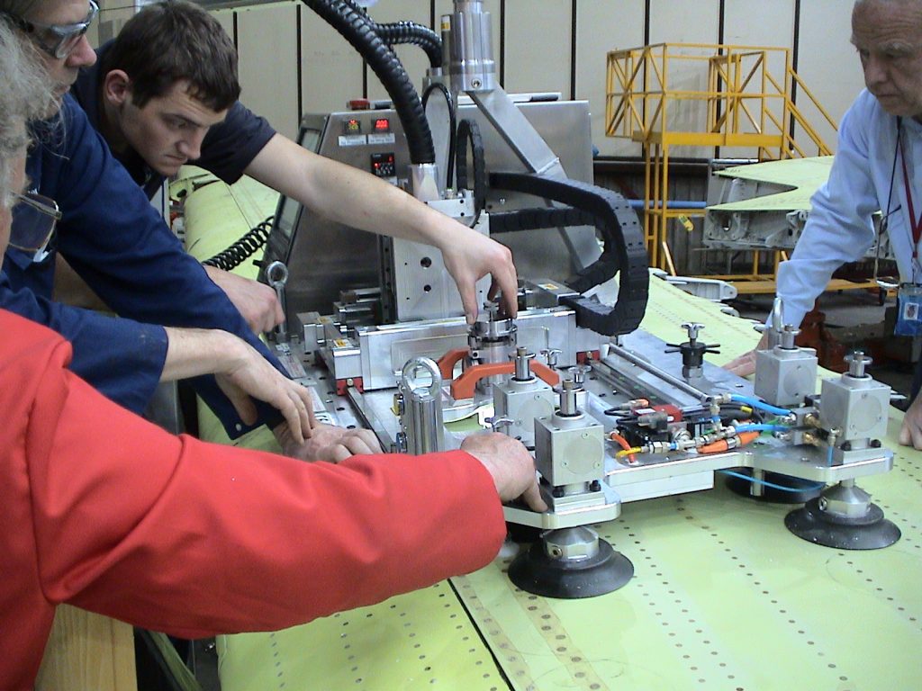
We have designed bespoke machines to aid many engineering operations. This can be anything from flap track slots and over-wing refuelling holes to fuselage interface machining for horizontal stabiliser installation (pictured right)
Three Axis CNC Machines
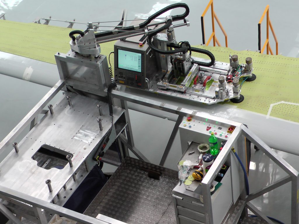
At the top of this image is a three Axis CNC profiling machine with a Computer Controlled Operator Platform shown in Neutral Balance Condition on an Airbus wing. This neutral balance condition is controlled by the platform.As this machine is controlled by a standard CNC system, it is capable of machining any required three dimensional profile by inputting a new programme.
To the left of the picture is a complete replica wing section, used for operator training and programme trials. When the machine is not in use, it is stored in cups located above this complete replica wing section.In this condition the complete system is easily transported from site to site.
Normality Alignment to Compound Profile
This machine also incorporates built in Lasers for XY Location and Low Power High Brightness Lamps for work piece examination and measurement.
Normality alignment is adjusted with three legs and the complete machine is fixed in position with eight Vacuum Cups. The Vacuum pressure for these cups is generated on machine.
Full condition monitoring is employed to guarantee that all systems are operating at the required level for successful product manufacture.
Cutting speed is 15,000 RPM with a feed of 1500mm/min in all directions.
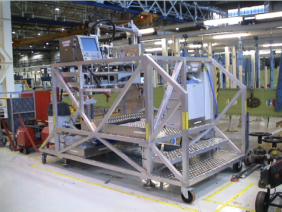
Mobile Machine Integration
This self contained platform for supporting a machine at all times is controlled by a PLC. This rigid structure is movable by hand and incorporates pneumatic jacks for total stability when in metal cutting mode. The PLC and CNC communicate with each other to ensure the total integrity of the machine.
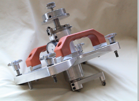
Compound Normality Gauge
To complement our CNC Machines we have Normality Aligment Gauging, shown here, which is located in a pre-determined position on a machine and provides facilities for aligning normal (perpendicular) to a spherical or compound curved surface.
With this same gauge the XY location can be confirmed following alignment.
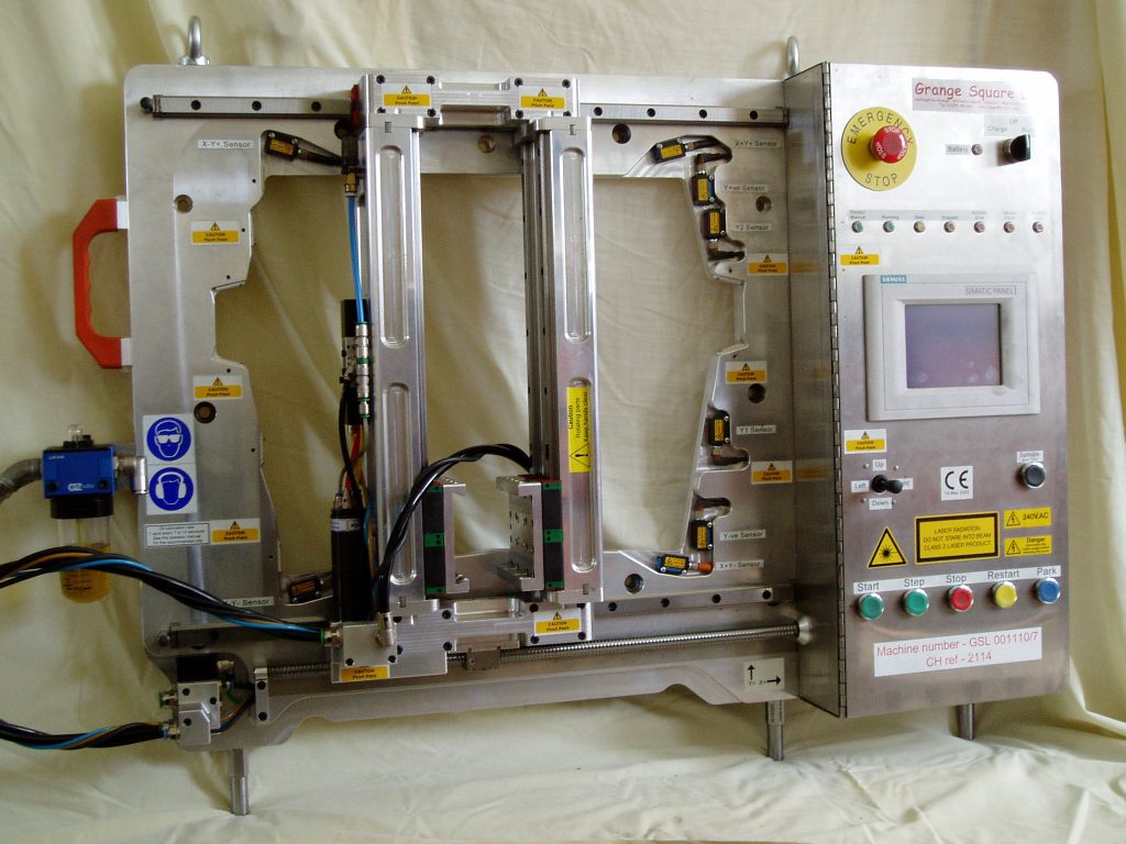
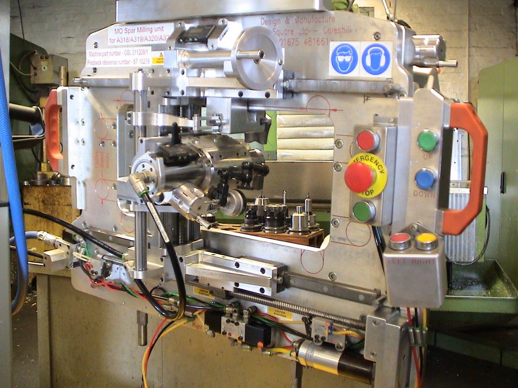
Semi-Automatic Machines
The above machine is an example of a Pylon Milling Machine.The complete system is controlled by a dedicated PLC System with Touch Screen Display. The milling path is controlled by inbuilt Lasers and the milling cutter follows the various Laser guided locations.
Power is derived from 230V AC / 110V AC and Air at 95 PSI/6.5 Bar. Battery Backup is included and the system will run for three hours without electrical input on its internal battery.
Cutting speed is 15,000 RPM with a feed of 2000mm/min.
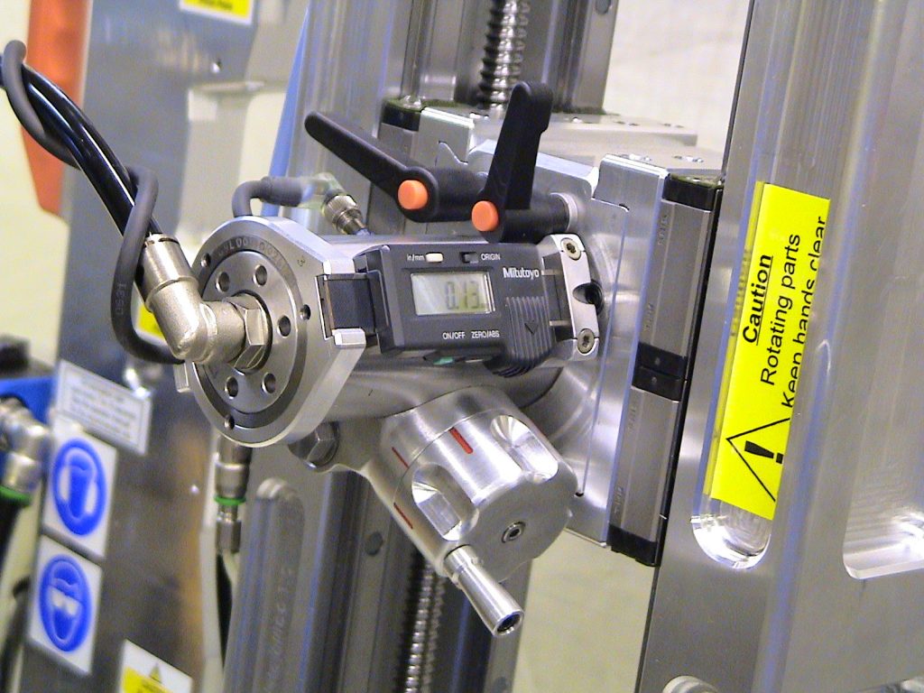
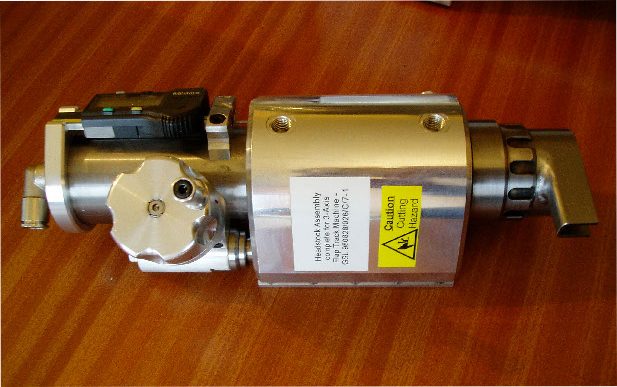
Typical Headstock Installation
Z Depth control is manual and measured with a Digital Read Out.
The resolution is 0.01mm.
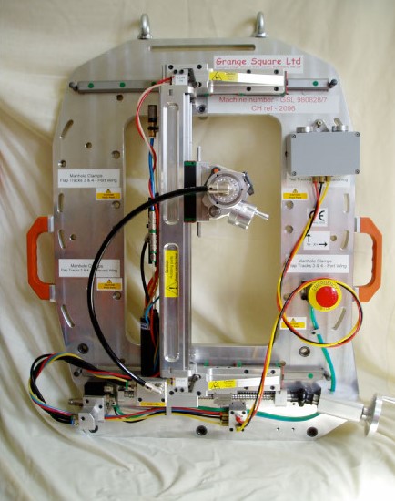
Manual Milling Machine
Machine with Manual X and Powered Y Axis
The above example is for a Flap Track Plateau Milling. The milling path is controlled manually between mechanical stops. Z Depth control is manual and measured with a Digital Read Out boasting a resolution of 0.01mm.
Power is derived from Air at 95 PSI/6.5 Bar. Cutting speed is 15,000 RPM with a feed of 2000mm/min.
Total weight is 65Kg, allowing for ease of portability.
6 Axis Machine with Powered X Axis
The machine to the left is designed for Rear Spar Machining. It is a six Axis machine with a number of axes mechanically interrelated to enable profiles to be machined, which match existing profiles on a ‘Blend Operation’
The Axes are defined as X, Y, Z, A, U & W.
This machine is hand operated with the X Axis power driven by button control.
A & Z Axis control is manual and measured with a Digital Read Out to resolution is 0.01mm & 0.01°
The machine weight is 68Kg and is supported at all times on a ‘Mini Powered Buggy’
Power is derived from Air at 95 PSI & Cutting speed is 15,000 RPM with a feed of 2000mm/min
Typical Headstock
Typical Headstock assembly with DRO and manual in feed for depth control.
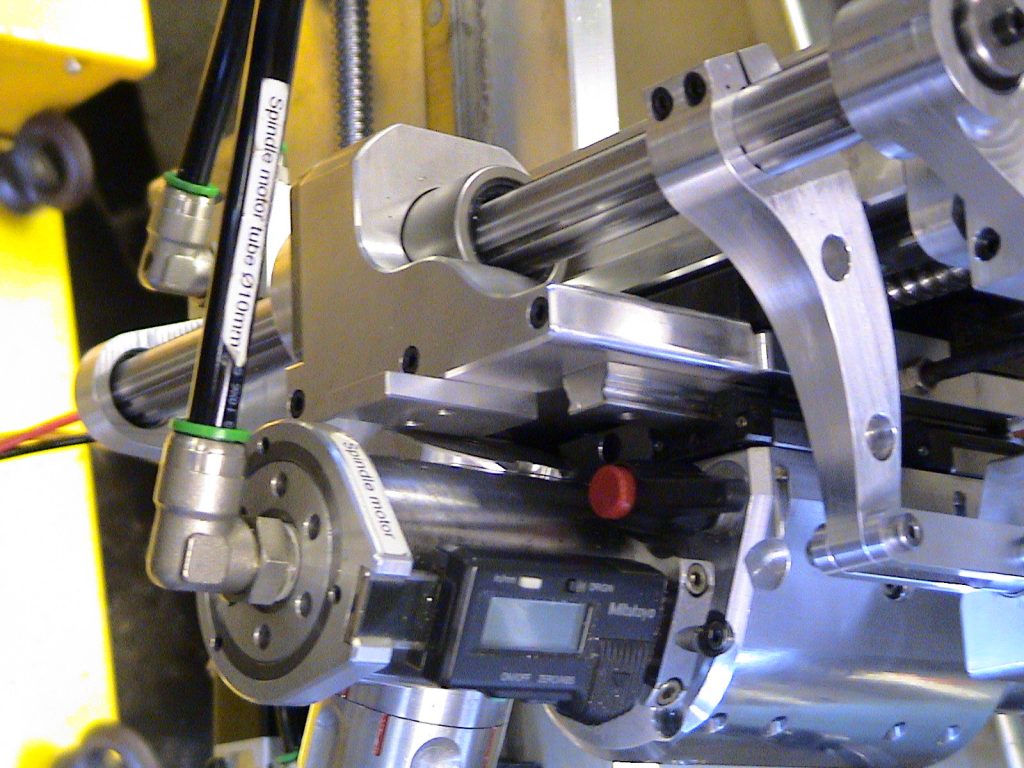
The spindle motor is integrated into the quill and the lubricated exhaust air from this motor is ducted around the milling cutter to aid with the removal of swarf and to provide a mist cutting lubricant.
Interconnected W Axis
W Axis control is through a Splined-Interconnecting shaft.
Typical Headstock Installation
Z Depth control is manual and measured with a Digital Read Out. The resolution is 0.01mm.
This website uses cookies to improve your experience. By continuing you agree to their usage, but you can opt-out if you wish. Cookie settingsACCEPT Find Out More
Privacy & Cookies Policy
Privacy Overview
This website uses cookies to improve your experience while you navigate through the website. Out of these cookies, the cookies that are categorized as necessary are stored on your browser as they are essential for the working of basic functionalities of the website. We also use third-party cookies that help us analyze and understand how you use this website. These cookies will be stored in your browser only with your consent. You also have the option to opt-out of these cookies. But opting out of some of these cookies may have an effect on your browsing experience.
Necessary cookies are absolutely essential for the website to function properly. This category only includes cookies that ensures basic functionalities and security features of the website. These cookies do not store any personal information.
Any cookies that may not be particularly necessary for the website to function and is used specifically to collect user personal data via analytics, ads, other embedded contents are termed as non-necessary cookies. It is mandatory to procure user consent prior to running these cookies on your website.